Working with Cells
Contents
- 1. Selecting cells
- 1.1. Step-by-step instructions for selecting a single cell
- 1.2. Step-by-step instructions for selecting multiple cells
- 1.3. Step-by-step instructions for selecting upstream cells
- 1.4. Step-by-step instructions for selecting upstream channel cells
- 1.5. Step-by-step instructions for selecting upstream overland cells
- 2. Changing cell type
- 3. Editing flow direction
- 4. Editing cell properties
- 5. Naming cells
- 6. Changing cell color
Selecting cells
Selecting cells or groups of cells is necessary to perform many functions within Vflo™. When a cell or cells are selected, any changes made to hydraulic properties, infiltration parameters, calibration factors, etc. will be made for the selected cell or cells, only. There are several different means of selecting cells, for user convenience.
Step-by-step instructions for selecting a single cell
1. Choose the Selection ![]() tool from the Vflo™ Toolbar.
tool from the Vflo™ Toolbar.
- As an alternative, use the shortcut key, CTRL + 4, or select Edit | Selection.
2. Click on the desired cell.
Step-by-step instructions for selecting multiple cells
1. Choose the Selection ![]() tool from the Vflo™ Toolbar (or press CTRL +4).
tool from the Vflo™ Toolbar (or press CTRL +4).
2. Holding the SHIFT key, click on all desired cells.
Step-by-step instructions for selecting upstream cells
1. Choose the Selection ![]() and the Select upstream cells
and the Select upstream cells ![]() tools from the Vflo™ Toolbar.
tools from the Vflo™ Toolbar.
- As an alternative, select Edit | Upstream Cell Selection.
- Both the Selection and the Select upstream cells tools will be highlighted, as shown below.
- In addition, the Select upstream cells
 cursor will become active.
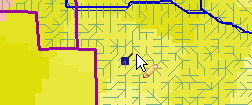
2. Click the desired cell. All cells upstream of that cell will be highlighted.
Shortcut for selecting upstream cells
1. Choose the Selection ![]() tool by pressing CTRL + 4.
tool by pressing CTRL + 4.
2. Holding the CTRL key, click on the desired cell. All upstream cells will be highlighted.
Step-by-step instructions for selecting upstream channel cells
1. Choose the Selection ![]() and the Select upstream channel cells
and the Select upstream channel cells ![]() tools from the Vflo™ Toolbar.
tools from the Vflo™ Toolbar.
- As an alternative, select Edit | Upstream Channel Cells Selection.
- Both the Selection and the Select upstream channel cells tools will be highlighted. The Select upstream channel cells
 cursor will become active.
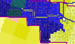
2. Click the desired cell. All channel cells upstream of that cell will be highlighted.
- Overland and other cell types will not be selected.
Shortcut for selecting upstream channel cells
1. Choose the Selection ![]() tool by pressing CTRL + 4.
tool by pressing CTRL + 4.
2. Holding the CTRL and ALT keys simultaneously, click the desired cell. All upstream channel cells will be selected.
Step-by-step instructions for selecting upstream overland cells
Selecting upstream overland cells can effectively isolate specific watershed areas that drain to a channel between upstream/downstream points.
1. Choose the Selection ![]() and the Select upstream overland cells
and the Select upstream overland cells ![]() tools from the Vflo™ Toolbar.
tools from the Vflo™ Toolbar.
- As an alternative, select Edit | Upstream Overland Cell Selection.
- Both the Selection and the Select upstream overland cells tools will be highlighted. The Select upstream overland cells
 cursor will become active.
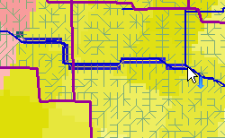
2. Click the desired cell. All overland cells upstream of that cell will be highlighted.
- Channel cells will not be selected.
Shortcut for selecting upstream overland cells
1. Choose the Selection ![]() tool by pressing CTRL + 4.
tool by pressing CTRL + 4.
2. Then, select all upstream cells by pressing the CTRL key, while clicking on the desired cell.
3. Finally, de-select channel cells.
- Holding the CTRL, ALT, and SHIFT keys simultaneously, click on the desired cell again. This will leave only upstream overland cells selected.
Changing cell type
For detailed information on the characteristics of each cell type, see the Cell types and Hydraulic properties pages.
Step-by-step instructions
1. Select a cell or group of cells.
2. Open the Hydraulics panel.
- Click on the Hydraulics panel located on the right side of the Vflo™ interface.
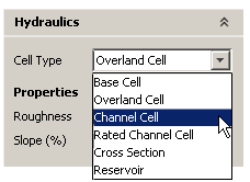
3. Open the Cell Type drop down menu.
- Select the desired cell type, as shown at right.
Editing flow direction
Depending on the resolution of the DEM from which the drainage network (flow direction grid) is drawn, flow directions may need to be edited to better represent actual runoff routing conditions. There are two different methods of editing flow direction, as described below.
For instructions on drawing a flow direction map on a blank Vflo™ grid, see Drawing a flow direction map.
Step-by-step instructions using the Flow Direction field
1. Select a cell.
2. Locate the Flow Direction field at the top right of the Vflo™ interface.
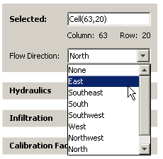 3. From the Flow Direction drop down menu, select the desired flow direction.
- Circular loops and other inappropriate drainage patterns will not be permitted.
Step-by-step instructions using the Draw cell connections tool
1. Select the Draw cell connections ![]() tool from the Vflo™ Toolbar.
tool from the Vflo™ Toolbar.
- As an alternative, select Edit | Draw, or use the shortcut key: CTRL + 3.
2. Click the cell for which flow direction is to be changed.
- Drag the Draw cell connections tool toward the adjoining cell to which runoff should be routed.
Editing cell properties
The conditions represented in Vflo™ and those in the real world may differ slightly. For instance, the infiltration parameters for a small group of cells may have changed due to urbanization. In these cases, editing of cell properties is recommended. There are two methods for editing cell parameters:
- 1. Manually editing cell properties through the Hydraulics and Infiltration panels.
- 2. Importing parameter maps for a cell or cells using Tools | Import ASCII.
 When editing cell properties for more than one cell at a time, it is important to realize that changes made to parameter values will apply to all selected cells. When multiple cells are selected, Vflo™ only exhibits information for one cell: the first cell that was selected. Some selected cells may have different parameter values than those shown in the Hydraulics, Infiltration, and Calibration Factors panels, however. When values are changed, all selected cells will take on the new values.
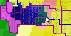
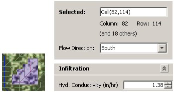
See the image at right for an example of this principle. In the basin model shown on the left, the Selection ![]() tool and the Select upstream cells
tool and the Select upstream cells ![]() tool have been used together to select all cells upstream of Cell(82,114). The Infiltration panel shows a hydraulic conductivity value of "1.38". This is the hydraulic conductivity value for Cell(82,114), only. The other 18 cells selected, as indicated by the text "(and 18 others)" in the Selected Cell panel at top, may have different values. When the hydraulic conductivity value is changed, the hydraulic conductivity values for all 19 cells selected will be changed to the new value.
tool have been used together to select all cells upstream of Cell(82,114). The Infiltration panel shows a hydraulic conductivity value of "1.38". This is the hydraulic conductivity value for Cell(82,114), only. The other 18 cells selected, as indicated by the text "(and 18 others)" in the Selected Cell panel at top, may have different values. When the hydraulic conductivity value is changed, the hydraulic conductivity values for all 19 cells selected will be changed to the new value.
Similarly, when importing parameter maps through the Tools menu, it is important to remember that importing a flow direction, roughness, or any other map will replace the values for that specific parameter in all cells except in cells where the imported parameter map contains no data values. In addition, importing an ASCII file may change certain cell types unless precautionary steps are taken. For example, if an imported channel width map contains values for a grid location established as a rated channel cell, the rated channel cell will be changed to a channel cell with trapezoidal channel properties. To avoid accidental changes to parameter values and cell types, be careful to import ASCII maps containing data only for desired cells.
Step-by-step instructions for using Hydraulics and Infiltration panels
1. Select the cell or group of cells for which changes are to be made.
2. Open the Hydraulics panel.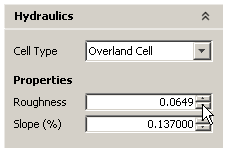
- Click on the Hydraulics panel, located on the right side of the Vflo™ interface.
3. Manually change Hydraulics values.
- Parameter fields are located beneath the Properties heading in the Hydraulics panel. To change a parameter value, click within the field and use the keyboard to type in new values. Alternately, the Up and Down arrows located at the right of each parameter field may be used to raise and lower values by one decimal point. In the image at right, the Roughness value for a channel cell has been edited using the Down arrow.
4. Open the Infiltration panel.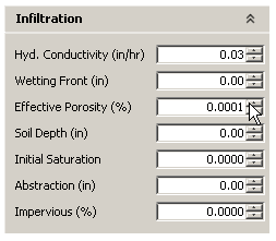
- Click on the Infiltration panel, located on the right side of the Vflo™ interface.
5. Manually change Infiltration values.
- Infiltration parameter values for the selected cell(s) are featured in the Infiltration panel. To change an infiltration parameter value, click within the field and type in new values, or use the Up and Down arrows as described above.
Step-by-step instructions for using parameter maps
1. Import a parameter map.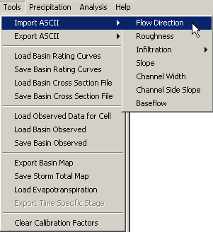
- Select Tools | Import ASCII. A drop down menu gives the option of loading the following parameter maps: Flow direction, Roughness, Infiltration (Hydraulic conductivity, Wetting front, Effective porosity, Soil depth, Initial saturation, Impervious, Abstraction), Slope, Channel width, Channel side slope, and Baseflow. Select the desired parameter map type.
- In the Import Map window that appears, navigate to the appropriately developed and formatted parameter map, then click Open.
Naming cells
By default, cells are named by their grid location. For example, a cell located at grid point (53,21) will be named "Cell(53,21)". It may be useful to rename key cells, such as watch points, as the cell name will identify the cell in the watch points list, the Results Manager, hydrograph windows, and several other locations.
Step-by-step instructions
1. Locate the Selected Cell field at the top right of the Vflo™ interface.
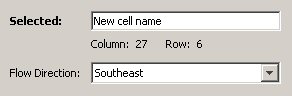 2. Delete the default title and type in the desired cell name.
Changing cell color
For instructions on changing cell color, see here.